Product Description
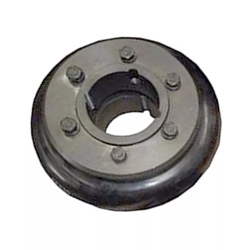
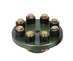
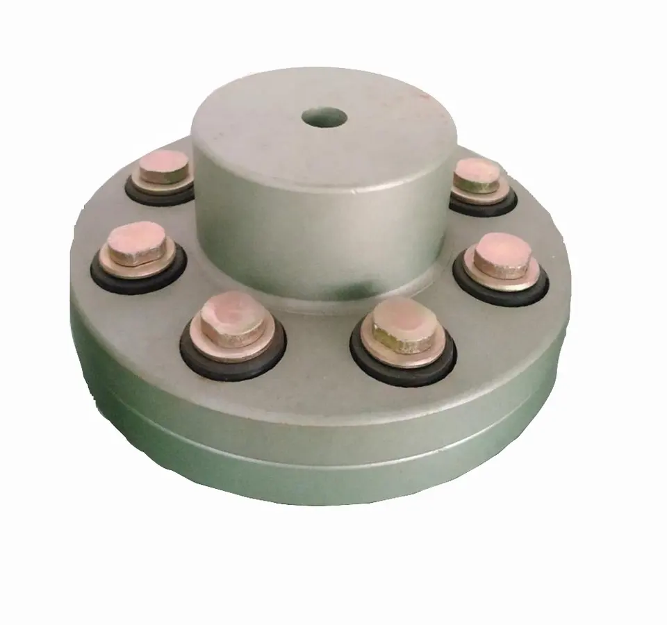
hydraulic flexible coupling
Specification:
| PART NO | THREAD E | HOSE BORE | DIMHangZhouONS | |||
| DN | DASH | A | C | S2 | ||
| 24211-04-04 | 9/16″×18 | 6 | 04 | 22.5 | 8.5 | 19 |
| 24211-04-05 | 9/16″×18 | 8 | 05 | 22.5 | 8.5 | 19 |
| 24211-04-06 | 9/16″×18 | 10 | 06 | 22.5 | 8.5 | 19 |
| 24211-06-04T | 11/16″×16 | 6 | 04 | 23.5 | 10 | 22 |
| 24211-06-05T | 11/16″×16 | 8 | 05 | 23.5 | 10 | 22 |
| 24211-06-06 | 11/16″×16 | 10 | 06 | 25.5 | 10 | 22 |
| 24211-06-08 | 11/16″×16 | 12 | 08 | 26 | 10 | 22 |
| 24211-08-05T | 13/16″×16 | 8 | 05 | 25 | 11 | 27 |
| 24211-08-06T | 13/16″×16 | 10 | 06 | 25 | 11 | 27 |
| 24211-08-08 | 13/16″×16 | 12 | 08 | 28 | 11 | 27 |
| 24211-08-10 | 13/16″×16 | 16 | 10 | 29 | 11 | 27 |
| 24211-10-08T | 1″×14 | 12 | 08 | 29.5 | 11 | 30 |
| 24211-10-10T | 1″×14 | 16 | 10 | 33.5 | 11 | 30 |
| 24211-10-12 | 1″×14 | 20 | 12 | 33.5 | 11 | 30 |
| 24211-12-08T | 1.3/16″×12 | 12 | 08 | 30.5 | 12 | 36 |
| 24211-12-10T | 1.3/16″×12 | 16 | 10 | 31.5 | 12 | 36 |
| 24211-12-12T | 1.3/16″×12 | 20 | 12 | 33 | 12 | 36 |
| 24211-12-12 | 1.3/16″×12 | 20 | 12 | 35 | 12 | 36 |
| 24211-12-16 | 1.3/16″×12 | 25 | 16 | 36 | 12 | 36 |
| 24211-16-12T | 1.7/16″×12 | 20 | 12 | 35 | 14.8 | 41 |
| 24211-16-14T | 1.7/16″×12 | 22 | 14 | 34 | 14.8 | 41 |
| 24211-16-16T | 1.7/16″×12 | 25 | 16 | 35 | 14.8 | 41 |
| 24211-16-20 | 1.7/16″×12 | 32 | 20 | 39.5 | 14.8 | 41 |
| 24211-20-16T | 1.11/16″×12 | 25 | 16 | 35 | 15 | 50 |
| 24211-20-20W | 1.11/16″×12 | 32 | 20 | 39.5 | 15 | 50 |
| 24211-20-24W | 1.11/16″×12 | 40 | 24 | 39.5 | 15 | 50 |
| 24211-24-20T | 2″×12 | 32 | 20 | 36 | 14.8 | 60 |
| 24211-24-24T | 2″×12 | 40 | 24 | 36 | 14.8 | 60 |
The material are always carbon steel, stainless steel or brass, and the material can be customized.
The surface of the ferrules are smooth, zinc plating or others customized.
Features:
High functionality
Precise design
Durable
carbon material:
Plant:
Warehouse:
Other products:
| Swaged Metric Fittings | Mertic Flat Seal Fittings |
| Metric Multiseal Fittings | |
| Metric 60°Cone Seal Fittings | |
| Metric 74°Cone Seal Fittings | |
| Metric 24°Cone O-RING Seal L..T Fittings | |
| Metric 24°Cone O-RING Seal H.T.Fittings | |
| Metric Standpipe Straight Fittings | |
| JIS Metric 60°Cone Seal Fitting | |
| Swaged British Fittings | BSP O-RING Seal Fittings |
| BSP Flat Seal Fittings | |
| BSP Multiseal Fittings | |
| BSP 60°Cone Seal Fittings | |
| BSPT Fittings | |
| JIS BSP 60°Cone Seal Fittings | |
| Swaged American Fittings | SAE O-RING Seal Fittings |
| ORFS Flat Seal Fittings | |
| NPSM 60°Cone Seal Fittings | |
| JIC 74°Cone Seal Fittings | |
| NPT Fittings SAE Flange L.T. Fittiings | |
| SAE Flange H.T.Fittings | |
| Staplelok Fittings | Banjo Double connection |
| interlock Hose Fittings | |
| Ferrule | FERRULE for SAE100R1AT/ EN 853 1SN HOSE |
| FERRULE for SAE100R1A EN 853 1ST HOSE | |
| FERRULE for SAE100R2AT/DIN20571 2SN HOSE | |
| FERRULE for SAE100R2A/EN 853 2SN HOSE | |
| FERRULE for SAE100R1AT-R2AT,EN853 1SN-2SN and EN 857 2SC | |
| FERRULE for 4SP,4SH/10-16,R12-06-16 HOSE | |
| FERRULE for 4SH,R12/32 HOSE | |
| Metric Adapters | Metric Thread O-RING Face Seal Adapters |
| Metric Thread Bite Type Tube Adapters | |
| JIS Metric Thread 60°Cone Adapters | |
| Metric Thread 74°Cone Flared Tube Adapters | |
| British Adapters | BSP Thread 60°Cone Adapters |
| JIS BSP Thread 60°Cone Adapters | |
| BSPT Thread Adapters | |
| American Adapters | ORFS Adapters JIC 74°Cone Flared Tube Adapters |
| NPT Thread Adapters |
We carries a wide variety of hydraulic hose ferrule fittings in common size,used mainly for crimping hose fittings.More other type ferrule,fitting and hose please feel free to contact with us.
/* March 10, 2571 17:59:20 */!function(){function s(e,r){var a,o={};try{e&&e.split(“,”).forEach(function(e,t){e&&(a=e.match(/(.*?):(.*)$/))&&1

How do you install and align a flexible coupling properly to ensure optimal performance?
Proper installation and alignment of a flexible coupling are essential to ensure its optimal performance and longevity. Incorrect installation can lead to premature wear, increased vibrations, and potential equipment failure. Below are the steps to install and align a flexible coupling properly:
1. Pre-Installation Inspection:
Before installation, inspect the flexible coupling and its components for any visible damage or defects. Check that the coupling’s size and specifications match the application requirements. Ensure that the shafts and equipment connected to the coupling are clean and free from debris.
2. Shaft Preparation:
Prepare the shafts by removing any oil, grease, or contaminants from the surfaces that will come into contact with the coupling. Ensure that the shaft ends are smooth and free from burrs that could affect the fit of the coupling.
3. Coupling Hub Installation:
Slide the coupling hubs onto the shafts, ensuring they are positioned securely and evenly on each shaft. Use a lubricant recommended by the manufacturer to facilitate the installation and ensure a proper fit.
4. Alignment:
Proper alignment is critical for the performance and longevity of the flexible coupling. Align the shafts by checking both angular and parallel misalignment. Utilize precision alignment tools, such as dial indicators or laser alignment systems, to achieve accurate alignment. Follow the manufacturer’s alignment specifications and tolerance limits.
5. Tightening Fasteners:
Once the shafts are properly aligned, tighten the coupling’s fasteners to the manufacturer’s recommended torque values. Gradually tighten the fasteners in a cross pattern to ensure even distribution of the load on the coupling hubs. Avoid over-tightening, as it may cause distortion or damage to the coupling.
6. Run-Out Check:
After installation, perform a run-out check to verify that the coupling’s rotating components are balanced and aligned. Excessive run-out can lead to vibrations and reduce the coupling’s performance. If significant run-out is detected, recheck the alignment and address any issues that may be causing it.
7. Lubrication:
Ensure that the flexible coupling is adequately lubricated, following the manufacturer’s recommendations. Proper lubrication reduces friction and wear, enhancing the coupling’s efficiency and reliability.
8. Periodic Inspection and Maintenance:
Regularly inspect the flexible coupling for signs of wear, misalignment, or damage. Address any issues promptly to prevent further problems. Depending on the coupling type and application, scheduled maintenance may include re-greasing, re-alignment, or replacing worn components.
Summary:
Proper installation and alignment are crucial for ensuring the optimal performance and longevity of a flexible coupling. Following the manufacturer’s guidelines, inspecting the components, achieving accurate alignment, and using the appropriate lubrication are key steps in the installation process. Regular inspection and maintenance help to identify and address potential issues, ensuring the coupling continues to operate smoothly and efficiently in the mechanical system.

Can flexible couplings be used in precision manufacturing equipment, such as CNC machines?
Yes, flexible couplings can be used in precision manufacturing equipment, including CNC (Computer Numerical Control) machines. CNC machines require high accuracy and precision during operation to produce complex and intricate parts. Flexible couplings play a vital role in such equipment by providing various benefits that enhance their performance and reliability.
- Compensation for Misalignment: CNC machines often have multiple moving parts and axes that need precise alignment. Flexible couplings can accommodate small misalignments between these components, ensuring smooth and reliable power transmission without inducing additional stress or strain on the system.
- Vibration Damping: Precision manufacturing requires minimizing vibrations that could affect the quality of the finished product. Flexible couplings with damping properties can absorb and dissipate vibrations, resulting in better surface finishes and accuracy of the machined parts.
- Torsional Flexibility: CNC machines may experience torque fluctuations during acceleration, deceleration, or tool changes. Flexible couplings with torsional flexibility can handle these variations and prevent torsional vibrations from affecting the machining process.
- Backlash Compensation: Some types of flexible couplings, such as beam couplings, offer minimal or near-zero backlash. This characteristic is essential in CNC machines, as it helps maintain positional accuracy during direction changes and reversals.
- High Torque Transmission: CNC machines may require high torque transmission capabilities, especially in heavy-duty cutting or milling operations. Flexible couplings can handle substantial torque loads while still providing flexibility to address misalignments.
- Reduced Maintenance: With the ability to absorb shocks and compensate for misalignment, flexible couplings can extend the life of other mechanical components in the CNC machine, reducing overall maintenance requirements and downtime.
It’s important to select the appropriate type and size of flexible coupling based on the specific requirements of the CNC machine, including torque, speed, misalignment, and environmental conditions. Regular maintenance and inspection of the flexible couplings will ensure optimal performance and contribute to the overall precision and efficiency of the CNC machine.

How do you select the appropriate flexible coupling for a specific application?
Choosing the right flexible coupling for a specific application requires careful consideration of various factors to ensure optimal performance, reliability, and longevity. Here are the key steps to select the appropriate flexible coupling:
- Application Requirements: Understand the specific requirements of the application, including torque and speed specifications, misalignment conditions, operating environment (e.g., temperature, humidity, and presence of corrosive substances), and space limitations.
- Torque Capacity: Determine the maximum torque that the coupling needs to transmit. Choose a flexible coupling with a torque rating that exceeds the application’s requirements to ensure a safety margin and prevent premature failure.
- Misalignment Compensation: Consider the type and magnitude of misalignment that the coupling needs to accommodate. Different coupling designs offer varying degrees of misalignment compensation. Select a coupling that can handle the expected misalignment in the system.
- Vibration Damping: If the application involves significant vibrations, choose a flexible coupling with good damping properties to reduce vibration transmission to connected equipment and improve system stability.
- Environmental Factors: Take into account the environmental conditions in which the coupling will operate. For harsh environments, consider couplings made from corrosion-resistant materials.
- Torsional Stiffness: Depending on the application’s requirements, decide on the desired torsional stiffness of the coupling. Some applications may require high torsional stiffness for precise motion control, while others may benefit from a more flexible coupling for shock absorption.
- Cost and Life-Cycle Considerations: Evaluate the overall cost-effectiveness of the coupling over its expected life cycle. Consider factors such as initial cost, maintenance requirements, and potential downtime costs associated with coupling replacement.
- Manufacturer Recommendations: Consult coupling manufacturers and their technical specifications to ensure the selected coupling is suitable for the intended application.
- Installation and Maintenance: Ensure that the selected flexible coupling is compatible with the equipment and shaft sizes. Follow the manufacturer’s installation guidelines and recommended maintenance practices to maximize the coupling’s performance and longevity.
By following these steps and carefully evaluating the application’s requirements, you can select the most appropriate flexible coupling for your specific needs. The right coupling choice will lead to improved system performance, reduced wear on equipment, and enhanced overall reliability in various mechanical systems and rotating machinery.


editor by CX 2024-01-15