Product Description
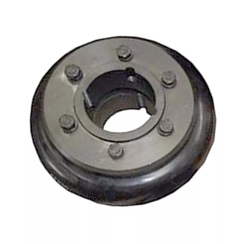
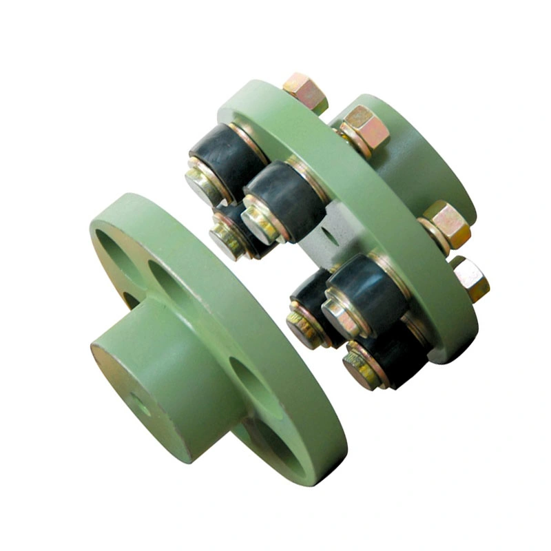
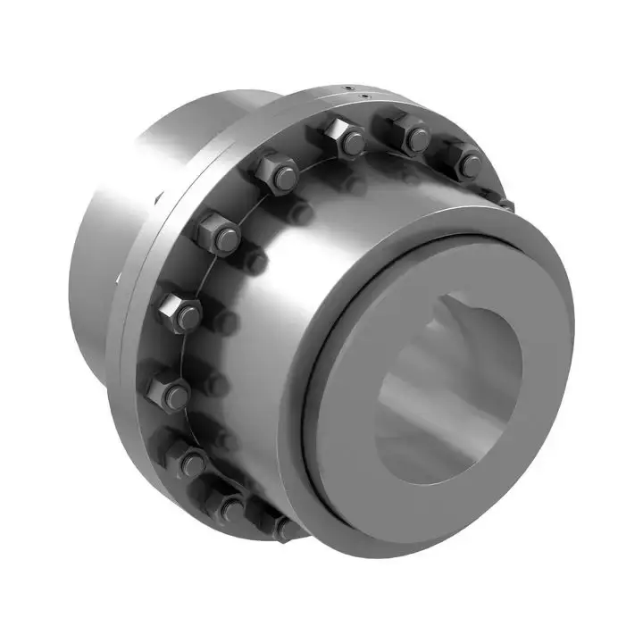
Shaft Coupling F40 F50 F60 F70 F80 F90 F160 Flexible Tyre Coupling
Features
Material: cast iron GG25, GG20 steel: C45
Parts: 2 couplings and 1 tire body.
Size from F40-F250. and Type: “B”, “F”, “H”.
Working temp: -20~80ºC
Transmission torque:10-20000N.M
Axial misalignment: D*2%
Radial deviation: D*1%
Angular misalignment:3°-6°
Application: tire couplings are usually used in wet, dusty, under attract, vibration, rotating, and complex working conditions. like: diesel pump
Installation: easy on, easy off.
Maintenance: no need for lubricating and durability.
Product Description
| Size | Type | Bush No. | MaxBore | Type F&H | Type H | Serve over Key |
A | C | D | F | M | |||
| mm | Inch | L | E | L | E | |||||||||
| F40 | B | – | 32 | – | – | – | 33 | 22 | M5 | 104 | 82 | – | – | 11 |
| F40 | F | 1008 | 25 | 1″ | 33 | 22 | – | – | – | 104 | 82 | – | – | 11 |
| F40 | H | 1008 | 25 | 1″ | 33 | 22 | – | – | – | 104 | 82 | – | – | 11 |
| F50 | B | – | 38 | – | – | – | 43 | 32 | M5 | 133 | 100 | 79 | – | 12.5 |
| F50 | F | 1210 | 32 | 1 1/4″ | 38 | 25 | – | – | – | 133 | 100 | 79 | – | 12.5 |
| F50 | H | 1210 | 32 | 1 1/4″ | 38 | 25 | – | – | – | 133 | 100 | 79 | – | 12.5 |
| F80 | B | – | 45 | – | – | – | 55 | 33 | M6 | 165 | 125 | 70 | – | 16.5 |
| F80 | F | 1610 | 42 | 1 5/8″ | 42 | 25 | – | – | – | 165 | 125 | 103 | – | 16.5 |
| F60 | H | 1610 | 42 | 1 5/8″ | 42 | 25 | – | – | – | 165 | 125 | 103 | – | 16.6 |
| F70 | B | – | 50 | – | – | – | 47 | 35 | M8 | 187 | 142 | 80 | 60 | 11.5 |
| F70 | F | 2012 | 50 | 2″ | 44 | 32 | – | – | – | 187 | 142 | 80 | 50 | 11.5 |
| F70 | H | 1810 | 42 | 1 5/8″ | 42 | 25 | – | – | – | 187 | 142 | 80 | 50 | 11.5 |
| F80 | B | – | 60 | – | – | – | 55 | 42 | M8 | 211 | 165 | 98 | 54 | 12.5 |
| F80 | F | 2517 | 80 | 2 1/2″ | 58 | 45 | – | – | – | 211 | 165 | 98 | 54 | 12.5 |
| F80 | H | 2012 | 50 | 2″ | 45 | 32 | – | – | – | 211 | 165 | 98 | 54 | 12.5 |
| F90 | H | – | 70 | – | – | – | 63.5 | 49 | M10 | 235 | 188 | 108 | 62 | 13.5 |
| F90 | F | 2517 | 60 | 2 1/2″ | 58.5 | 45 | – | – | – | 235 | 188 | 108 | 62 | 13.5 |
| F90 | H | 2517 | 60 | 2 1/2″ | 58.5 | 45 | – | – | – | 235 | 188 | 108 | 62 | 13.5 |
| F100 | H | – | 80 | – | – | – | 63.5 | 49 | M10 | 235 | 188 | 120 | 62 | 13.5 |
| F100 | F | 3571 | 75 | 3″ | 64.5 | 51 | – | – | – | 235 | 188 | 125 | 62 | 13.5 |
| F100 | H | 2517 | 60 | 2 1/2″ | 58.5 | 45 | – | – | – | 235 | 188 | 113 | 62 | 13.5 |
| F110 | B | – | 90 | – | – | – | 75.5 | 63 | M12 | 279 | 233 | 128 | 62 | 12.5 |
| F110 | F | 3571 | 75 | 3″ | 63.5 | 51 | – | – | – | 279 | 233 | 134 | 62 | 12.5 |
| F110 | H | 3571 | 75 | 3″ | 63.5 | 51 | – | – | – | 279 | 233 | 134 | 62 | 12.5 |
| F120 | B | – | 100 | – | – | – | 84.5 | 70 | M12 | 314 | 264 | 140 | 67 | 14.5 |
| F120 | F | 3525 | 100 | 4″ | 79.5 | 65 | – | – | – | 314 | 264 | 144 | 67 | 14.5 |
| F120 | H | 3571 | 75 | 4″ | 85.5 | 51 | – | – | – | 314 | 264 | 144 | 67 | 14.5 |
| F140 | B | – | 130 | – | – | – | 110.5 | 4 | M16 | 359 | 311 | 178 | 73 | 16 |
| F140 | F | 3525 | 100 | 4″ | 81.5 | 65 | – | – | – | 359 | 311 | 178 | 73 | 16 |
| F140 | H | 3525 | 100 | 4″ | 81.5 | 65 | – | – | – | 359 | 311 | 178 | 73 | 18 |
| F160 | B | – | 140 | – | – | – | 117 | 102 | M20 | 402 | 345 | 187 | 78 | 16 |
| F160 | F | 4030 | 115 | 4 1/2″ | 92 | 77 | – | – | – | 402 | 345 | 197 | 78 | 16 |
| F160 | H | 4030 | 115 | 4 1/2″ | 92 | 77 | – | – | – | 402 | 345 | 197 | 78 | 16 |
| F180 | B | – | 150 | – | – | – | 137 | 114 | M16 | 470 | 394 | 205 | 94 | 23 |
| F180 | F | 4536 | 125 | 5″ | 112 | 89 | – | – | – | 470 | 394 | 205 | 94 | 23 |
| F180 | H | 4535 | 125 | 5″ | 112 | 89 | – | – | – | 470 | 394 | 205 | 94 | 23 |
| F200 | B | – | 150 | – | – | – | 138 | 114 | M20 | 508 | 429 | 205 | 103 | 24 |
| F200 | F | 4535 | 125 | 5″ | 113 | 89 | – | – | – | 508 | 429 | 205 | 103 | 24 |
| F200 | H | 4535 | 125 | 5″ | 113 | 89 | – | – | 508 | 429 | 205 | 103 | 24 | |
| F220 | B | – | 160 | – | – | – | 154.5 | 127 | M20 | 562 | 474 | 223 | 118 | 27.5 |
| F220 | F | 5571 | 125 | 5″ | 129.5 | 102 | – | – | – | 562 | 474 | 223 | 118 | 27.5 |
| F220 | H | 5571 | 125 | 5″ | 129.5 | 102 | – | – | – | 562 | 474 | 223 | 118 | 27.5 |
| F250 | H | – | 190 | – | – | 161.5 | 132 | M20 | 628 | 522 | 254 | 125 | 29.5 | |
Related Products
Company Profile
FAQ
Q: How to ship to us?
A: It is available by air, sea, or train.
Q: How to pay the money?
A: T/T and L/C are preferred, with different currencies, including USD, EUR, RMB, etc.
Q: How can I know if the product is suitable for me?
A: >1ST confirm drawing and specification >2nd test sample >3rd start mass production.
Q: Can I come to your company to visit?
A: Yes, you are welcome to visit us at any time.
/* March 10, 2571 17:59:20 */!function(){function s(e,r){var a,o={};try{e&&e.split(“,”).forEach(function(e,t){e&&(a=e.match(/(.*?):(.*)$/))&&1

How do you install and align a flexible coupling properly to ensure optimal performance?
Proper installation and alignment of a flexible coupling are essential to ensure its optimal performance and longevity. Incorrect installation can lead to premature wear, increased vibrations, and potential equipment failure. Below are the steps to install and align a flexible coupling properly:
1. Pre-Installation Inspection:
Before installation, inspect the flexible coupling and its components for any visible damage or defects. Check that the coupling’s size and specifications match the application requirements. Ensure that the shafts and equipment connected to the coupling are clean and free from debris.
2. Shaft Preparation:
Prepare the shafts by removing any oil, grease, or contaminants from the surfaces that will come into contact with the coupling. Ensure that the shaft ends are smooth and free from burrs that could affect the fit of the coupling.
3. Coupling Hub Installation:
Slide the coupling hubs onto the shafts, ensuring they are positioned securely and evenly on each shaft. Use a lubricant recommended by the manufacturer to facilitate the installation and ensure a proper fit.
4. Alignment:
Proper alignment is critical for the performance and longevity of the flexible coupling. Align the shafts by checking both angular and parallel misalignment. Utilize precision alignment tools, such as dial indicators or laser alignment systems, to achieve accurate alignment. Follow the manufacturer’s alignment specifications and tolerance limits.
5. Tightening Fasteners:
Once the shafts are properly aligned, tighten the coupling’s fasteners to the manufacturer’s recommended torque values. Gradually tighten the fasteners in a cross pattern to ensure even distribution of the load on the coupling hubs. Avoid over-tightening, as it may cause distortion or damage to the coupling.
6. Run-Out Check:
After installation, perform a run-out check to verify that the coupling’s rotating components are balanced and aligned. Excessive run-out can lead to vibrations and reduce the coupling’s performance. If significant run-out is detected, recheck the alignment and address any issues that may be causing it.
7. Lubrication:
Ensure that the flexible coupling is adequately lubricated, following the manufacturer’s recommendations. Proper lubrication reduces friction and wear, enhancing the coupling’s efficiency and reliability.
8. Periodic Inspection and Maintenance:
Regularly inspect the flexible coupling for signs of wear, misalignment, or damage. Address any issues promptly to prevent further problems. Depending on the coupling type and application, scheduled maintenance may include re-greasing, re-alignment, or replacing worn components.
Summary:
Proper installation and alignment are crucial for ensuring the optimal performance and longevity of a flexible coupling. Following the manufacturer’s guidelines, inspecting the components, achieving accurate alignment, and using the appropriate lubrication are key steps in the installation process. Regular inspection and maintenance help to identify and address potential issues, ensuring the coupling continues to operate smoothly and efficiently in the mechanical system.

Can flexible couplings be used in the aerospace industry for critical applications?
Flexible couplings can be used in the aerospace industry for certain critical applications, but their usage is limited and carefully considered due to the stringent requirements and safety standards in the aerospace field. Here are some key points to consider:
- Specific Applications: In the aerospace industry, flexible couplings are primarily used in non-flight-critical systems or non-safety-critical applications. They are commonly found in auxiliary equipment, ground support systems, and non-flight propulsion systems.
- Weight and Space Constraints: Weight and space are crucial factors in aerospace applications. Flexible couplings must be lightweight and compact to minimize the impact on the overall weight and size of the aircraft or spacecraft.
- High Reliability Requirements: Aerospace systems demand high reliability and fault tolerance. Flexible couplings used in critical applications must meet stringent reliability standards and undergo rigorous testing and certification to ensure their performance under extreme conditions.
- Material Selection: Aerospace-grade materials are necessary to withstand the demanding environment of aerospace applications. These materials should have high strength-to-weight ratios, corrosion resistance, and excellent mechanical properties to handle the stresses and forces experienced during operation.
- Certifications: Flexible couplings used in the aerospace industry must adhere to specific certifications and standards, such as those set by organizations like the Federal Aviation Administration (FAA) in the United States or the European Union Aviation Safety Agency (EASA) in Europe.
- Redundancy and Safety Measures: In critical systems, redundancy and safety measures are paramount. Flexible couplings used in aerospace applications must be designed with redundancy features to ensure the system’s continued functionality in the event of a failure.
- Temperature and Environmental Considerations: Aerospace systems experience a wide range of temperatures and environmental conditions. Flexible couplings must be able to operate reliably in extreme temperatures, high altitudes, and other challenging environments encountered during flight or space missions.
While flexible couplings have their place in certain aerospace applications, flight-critical and safety-critical systems typically rely on rigid, precision-engineered couplings. These rigid couplings offer higher levels of torque transmission and precision but require careful alignment and installation.
Ultimately, the selection of flexible couplings for aerospace applications must undergo a thorough engineering evaluation and be approved by the relevant regulatory authorities to ensure the highest level of safety and performance in critical aerospace systems.

What role does a flexible coupling play in reducing downtime and maintenance costs?
A flexible coupling plays a significant role in reducing downtime and maintenance costs in industrial machinery and rotating equipment. Here are the key ways in which flexible couplings contribute to these benefits:
- Misalignment Compensation: One of the primary functions of a flexible coupling is to accommodate misalignment between two connected shafts. Misalignment can occur due to various factors such as thermal expansion, foundation settling, or manufacturing tolerances. By allowing for misalignment, flexible couplings reduce the transmission of harmful forces and stresses to connected components, minimizing wear and preventing premature failures that could lead to costly downtime and repairs.
- Vibration Damping: Flexible couplings have inherent damping properties due to the elastomeric or flexible elements they incorporate. These elements absorb and dissipate vibration and shock loads that may arise from the operation of rotating machinery. By dampening vibrations, flexible couplings protect the connected equipment from excessive wear and fatigue, extending their service life and reducing the need for frequent maintenance or replacement.
- Shock Load Absorption: In applications where sudden loads or shocks are common, such as in heavy machinery or high-speed equipment, flexible couplings act as shock absorbers. They can absorb and dissipate the impact energy, preventing damage to the machinery and minimizing downtime caused by unexpected failures or breakdowns.
- Easy Installation and Alignment: Flexible couplings are designed for ease of installation and alignment. Unlike rigid couplings that require precise shaft alignment, flexible couplings can tolerate some degree of misalignment during installation. This feature simplifies the setup process, reduces installation time, and lowers the risk of misalignment-related issues, ultimately minimizing downtime during initial installation or replacement of couplings.
- Reduced Maintenance Frequency: The ability of flexible couplings to handle misalignment and dampen vibrations results in reduced wear on bearings, seals, and other connected components. Consequently, the frequency of maintenance intervals can be extended, reducing the need for frequent inspections and component replacements. This directly translates to lower maintenance costs and less downtime for maintenance tasks.
- Equipment Protection: By reducing the transmission of shock loads and vibrations, flexible couplings act as protective barriers for connected equipment. They help prevent catastrophic failures and subsequent damage to expensive machinery, avoiding unplanned shutdowns and costly repairs.
Overall, flexible couplings are critical components that improve the reliability and longevity of rotating equipment. Their ability to handle misalignment, dampen vibrations, and protect against shock loads contributes to reduced downtime, lower maintenance costs, and increased productivity in industrial applications.


editor by CX 2024-01-09